WIRES FOR RACE CARS – PART THREE
January 1, 2026
Wire Strippers
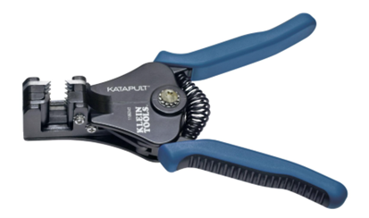
- Klein Tools Automatic Wire Strippers.png (78.83 KiB) Viewed 11156 times
Klein Tools Automatic Wire Strippers Part Number: KLE-11063-W
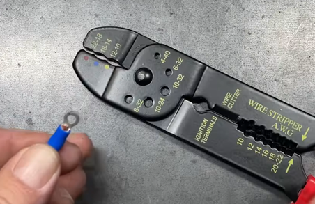
If you don’t want to pop for this really nice Klein tool above, this one below will work. Very similar to the one I use:
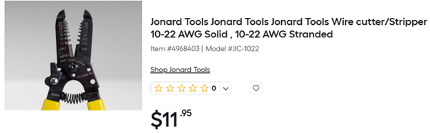
- Wire Strippers.png (56.82 KiB) Viewed 11156 times
Whatever wire striper you buy, make sure that it has a locking feature, you don’t want this open floating around in your toolbox. I found this at Lowes.
TERMINALS
In designs requiring high reliability, crimping is preferable to soldering but with the proviso that all crimped joints be inspected and pins be checked that they are fully latched (the latches can be seen on the correct side of the housing).
Soldering is just pouring a different metal in the gaps between the strands. Soldered joints are susceptible to fracturing especially on the surface of the pin where the different materials expand and contract at different rates and where mechanical stress has the largest leverage.
In an application which has large temperature changes or high vibration, soldering is particularly unreliable.
Another issue with soldering stranded wires is that the solder wicks up the strands, turning the stranded wire into solid wires. That makes it susceptible to metal fatigue.
Understanding Ring Terminals
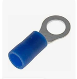
- Ring Terminals.png (20.44 KiB) Viewed 11156 times
Ring terminals
Also referred to as ring connectors, serve as electrical connectors for attaching a wire to a stud or screw. They find extensive use in automotive, marine, and industrial settings because of their reliability and ease of use. Featuring a ring-shaped end that fits over a stud or screw, as well as a crimping end that attaches to the wire, these terminals facilitate secure electrical connections.
Ring terminals are used instead of fork terminals for more secure, permanent connections that resist vibration, while fork terminals are used for quick, easy connections where a connection needs to be made or broken frequently. Ring terminals are more secure because the closed loop provides a stronger connection to a screw or stud, making them ideal for high-vibration environments like industrial machinery or automotive applications
Choosing the right ring terminal involves considering factors such as the wire size, stud size, material, and insulation type. Each of these factors plays a critical role in the performance and safety of the electrical connection.

- Locking forks.png (3.33 KiB) Viewed 11156 times
Locking Fork
Locking forks carry nubbed ends which snap onto the stud. That is why they are also known as “snap-on” fork terminals. The nubs create a space that is smaller than the diameter of the stud they are being attached to. This means you must push them past the point of resistance to get them to snap on. Don’t worry, they are designed for this, and as such the process causes no damage to the terminal or the stud. This locking action decreases the chances that they will fall off or come loose over time. Locking forks are a solid choice if you know you may be making changes to the electrical system in the future.
After you have finished attaching the terminals to your electronics, I recommend adding a small amount of clear RTV on the nut or screw terminal. This will keep the nut or screw from coming loose. You can easily remove the RTV if you need to remove the wire terminal.
Butt Connectors
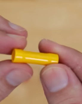
- Butt Splice connector-typical.jpg (10.86 KiB) Viewed 11156 times
For inline wire splices, butt connectors (also called butt splices) join two wires end-to-end. They come in non-insulated or insulated versions, often heat-shrinkable.
Crimp each side of the splice onto one wire, then shrink-wrap the splice. This leaves a sealed, strain-relieved joint. Butt connectors are often used in automotive and marine applications. Watch out: use the correct AWG range – for example, don’t use a yellow AWG 12–10 butt on an AWG 18 wire, even if it “fits,” as the copper-to-copper contact area will be poor.
I have added the “Butt Connectors” in this description of connectors. However, I strongly recommend that you not use them unless it is a field repair. i.e. it’s race day and the damn wire broke. The more connectors in a circuit, the more chances of failure.
INSERTING THE WIRE INTO THE TERMINAL
• To twist or not
Here’s a non-obvious bit: the stronger you twist a bunch of strands, the shorter and fatter the bunch gets. So a manufactured wire’s final size is designed to be correct at the final twist.
So, why not twist by hand? Well, usually, people hand-twist far stronger than the factory twist. This means the strand bundle gets a bit fatter and shorter. But also, when we do it by hand, we usually use too much pressure and disturb the lay of the strands, introducing larger and more irregular air gaps. So, the end result is a bundle with the strands at uneven angles, with uneven gaps between them, and thus with uneven cross-section making the crimp less reliable.
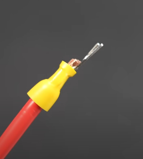
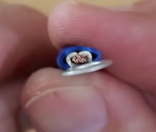
A small amount of the wire should protrude past the metal part of the terminal as seen in the photos below.
CRIMPING
Crimping is the process of joining two conductors (wire or cable) by deforming a metal connector tightly around them. When done correctly, crimping creates a permanent, secure electrical connection that is more reliable than soldering. Proper crimps ensure a consistent current flow and can withstand vibrations and pulling in harsh environments.
The core of any good crimp job is the right crimping tool matched to the connector type and wire gauge.
I can’t recommend this crimper
- Bad Crimper.png (297.53 KiB) Viewed 11156 times
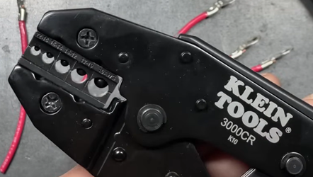
- Good Klien Crimper.png (189.92 KiB) Viewed 11156 times
I recommend this tool for crimping both insulated and non-insulated terminals
• This tool has replaceable jaws for both insulated and non-insulated
Choose terminals for the wire AWG and application (e.g. heat-shrink insulated for moisture, marine-grade if needed)
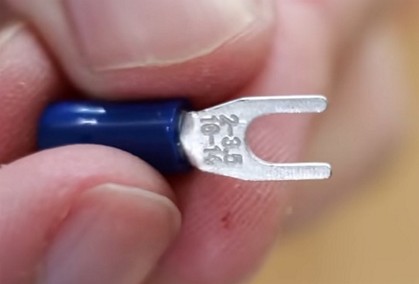
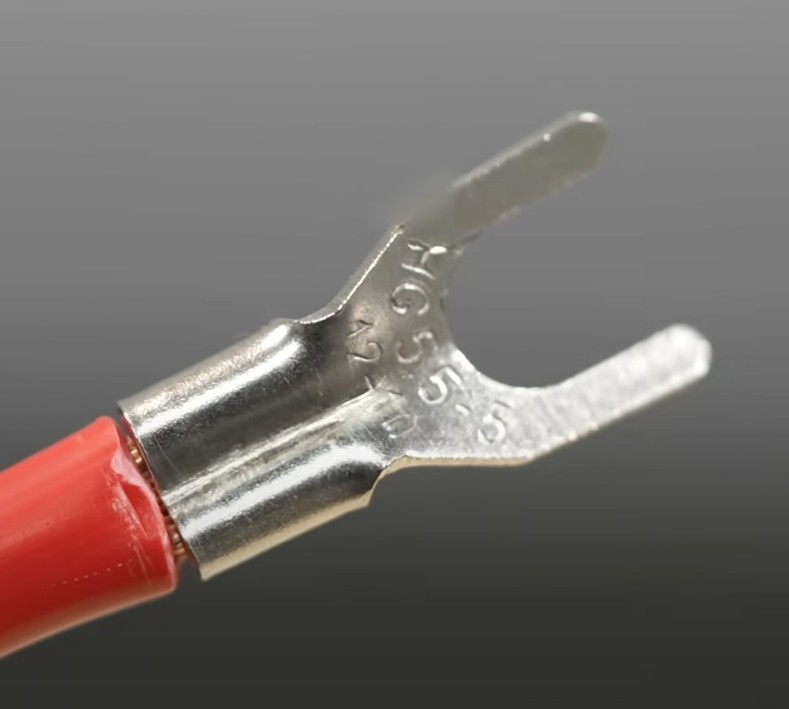
- Here is a fork terminal showing the wire gauge.jpg (16.65 KiB) Viewed 11156 times
Here is a fork terminal showing the wire gauge (18-16), that will work with this terminal.
Use the color-code chart below for heat-shrink butt/ferrule terminals:
Wire Gauge (AWG)...Connector Color.........Typical Use
22–18............................Red.......................Small wires (ground wires, signal)
16–14............................Blue......................Medium wires (12–14 AWG splices)
12–10............................Yellow....................Large wires (battery cables, high
......................................................................Current circuits)
- An example of a good crimp on a insulated terminal.jpg (19.17 KiB) Viewed 11156 times
- An example of a good crimp.jpg (9.67 KiB) Viewed 11156 times
Showing good crimp on insulated terminals
- What a good crimp should look like-bottom view.jpg (42.6 KiB) Viewed 11156 times
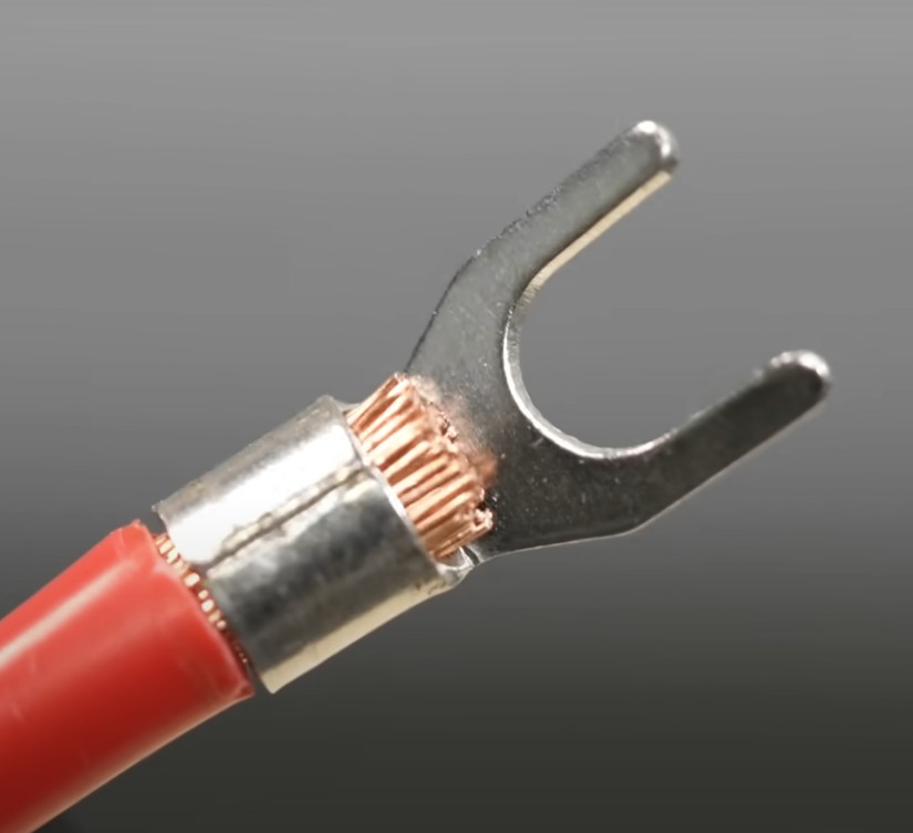
- What a good crimp should look like-top view.jpg (44.48 KiB) Viewed 11156 times
Showing good crimp on both sides of a fork terminal
Inspecting Crimps
A final check is crucial. Perform a pull test on each crimp: grip the wire near the connector and tug hard. The wire should not pull out. If it does, the crimp is unacceptable. Also inspect the die imprint: it should be full and even. A good crimp (like the rings in the photos above) shows a uniform pattern.
Warning!
Pliers are not crimpers! Neither are hammers, vises, needle nose pliers or flat rocks. A good crimper when used correctly will make a cold weld between the wire and the barrel of the connector. If you were to cut a well-executed crimp in half you would see a solid form of wire and connector. Using the wrong tool will not achieve a good crimp!
